
Application Engineering
Design Considerations
The addition of expansion joints in a piping system introduces reaction forces produced by the expansion joint that must be accommodated in the design of the piping system.
 Spring Force
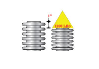
Expansion joints behave in a manner that is similar to a spring; as movement occurs, expansion joints produce a resistive force. This resistance is stated as spring rate and measured as the force required to deflect the bellows 1” in the axial or lateral direction; or inch-lbs./degree for angular rotation. Spring force is the spring rate times the deflection in inches.
Pressure Thrust
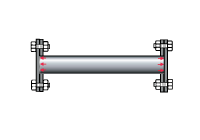 If we consider a pipe section with blind flanges attached at each end, it is obvious that internal pressure produces a thrust force against the flange surfaces in opposing directions, however the longitudinal rigidity of the pipe prevents elongation.
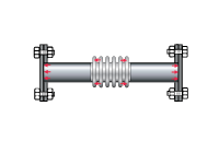 If we add an expansion joint in the center of the pipe, this rigidity is lost and the thrust force may overcome the spring resistance of the bellows, producing elongation and possibly uncorrugating of the bellows.
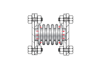 A pressurized bellows behaves like a hydraulic cylinder. Internal pressure bears against the walls of the convolutions, just as pressure bears against the face of a piston. This pressure produces a force that is equal to the internal pressure multiplied by the effective area of the bellows mean diameter ([ID + OD]/2) and will cause the flexible bellows to extend outward, unless it is restrained from doing so. In most pressure piping applications, pressure thrust is usually much greater than spring force.
Pipe Anchors
By adding fixed points in the piping system, referred to as main anchors, the expansion joint is prevented from extending. Pressure thrust force is directed into the immovable main anchor. Now the expansion joint is forced to compress or extend axially, solely in response to dimensional changes in the pipe segment located between these main anchors.
Anchor design requires the consideration of forces due to pressure thrust at system test pressure, which is customarily 1.5 times the design pressure. In addition, bellows spring forces produced by deflection, friction force due to pipe movement across contact surfaces, forces and moments resulting from wind loading, bending and other influences must be considered in the design of anchors.
Main Anchors
Main anchors are intended to anchor the pipe from motion in any direction.

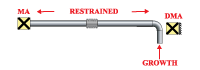
Directional main anchors
These anchors are, as the name implies, intended to anchor the piping system in one direction, while allowing movement to occur from a transverse direction.
Intermediate anchors
Intermediate anchors can isolate multiple expansion joints that are installed in series to accommodate large motions beyond the capability of a single expansion joint.
 This separation is required to insure that each expansion joint is able to function as intended and not be affected by the flexibility characteristics of adjoining units. Intermediate anchors react only to differences in spring force and are not exposed to pressure thrust.
Pipe Guides
With the addition of expansion joints and anchors, each pipe segment now behaves like a slender column under the compressive load of expansion joint pressure thrust and/or spring force bearing against the anchors. Bowing or buckling at the expansion joint may occur unless the pipe is properly guided.
Pipe guides are required to stabilize this slender column, preventing buckling and insuring that pipe growth is directed into the expansion joint as axial movement.
The first pipe guide must be located within four pipe diameters of each side of the expansion joint and a second guide placed within 10-14 pipe diameters of the first guide. Additional guides may be required based on guide spacing tables that consider diameter and system pressure. A convenient intermediate guide spacing chart is provided on page 23.
The recommendations given for pipe guides represent the minimum requirements for controlling pipelines which contain expansion joints and are intended to protect the expansion joints and pipe system from undefined external forces which could cause system failure.
Installation Misalignment
Installation misalignment reduces the total movement capacity of the expansion joint. Correction of misalignment should be completed prior to installation of the expansion joints. If misalignment can not be avoided, contact one of our engineers for guidance.
Concurrent Movements
Expansion joint movement capacity is listed in this website as the non-concurrent capacity for each type of movement. Axial, lateral and angular movements usually occur simultaneously, therefore it is essential that the concurrent movement capacity of the expansion joint be determined. This may be calculated by determining the required percentage of non-concurrent capacity required to meet each type of specified motion. The sum of these percentage values should be equal to or less than 1.0.