
Installation Instructions
Senior Flexonics Expansion Joints are fully inspected at the factory and are packaged to arrive at the job site in good condition. Please, immediately upon receipt at the job site, verify that there is no freight damage; i.e., dents, broken hardware, loose shipping bars, etc.
Because the bellows expansion joint is required to absorb thermal and/or mechanical movements, the bellows element must be constructed of a relatively thin gauge material. This requires special installation precautions. The following steps should be taken prior to installation of the expansion joint into the pipeline or duct.
- The opening into which the expansion joint will be installed should be examined to verify that the opening for which the expansion joint was designed does not exceed the installation tolerances designated by the designer and/or purchaser. If the opening exceeds the tolerance, notify Senior Flexonics at once for a disposition.
- The attachment edges of the pipe or duct should be smooth, clean, and parallel to each other.
- The area around the expansion joint should be cleared of any sharp objects or protrusions. If not removable, they should be noted so they can be avoided.
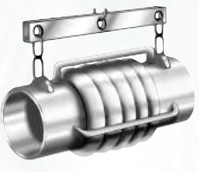
- Expansion joints provided with lifting lugs should be lifted only by the designated lifting lugs. SHIPPING BARS (PAINTED YELLOW) ARE NOT DESIGNED TO BE LIFTING DEVICES. NEVER USE A CHAIN OR ANY OTHER HANDLING DEVICES DIRECTLY ON THE BELLOWS ELEMENT OR BELLOWS COVER. For expansion joints not provided with lifting lugs (i.e., less than 500 lbs.), the best lifting method should be evaluated at the time of installation.
- The shipping bars are installed on an expansion joint to maintain shipping length and give the expansion joint stability during transit and installation. DO NOT REMOVE THE SHIPPING BARS UNTIL THE INSTALLATION IS COMPLETE.
Installation:
The following precautions must be taken when installing an expansion joint:
- Remove any protective covering from the ends of expansion joint. Plywood covers may have been used to protect flanges or weld ends. Check inside expansion joint for dessicant bags or any other material.
- When a flow liner is installed in the expansion joint, orient the expansion joint with FLOW ARROW POINTING IN DIRECTION OF FLOW.
- Using lifting lugs, lift joint to desired location and position into pipeline or ducting.
- Weld end expansion joints.(a) PRIOR TO WELDING, COVER THE BELLOWS ELEMENT WITH A CHLORIDE FREE FIRE RETARDANT CLOTH. This is to prevent arc strikes, weld splatter, etc. from damaging the bellows element.(b) Using the proper electrode, weld the expansion joint to adjacent piping. DO NOT USE BELLOWS TO CORRECT FOR MISALIGNMENT OF PIPING UNLESS THIS HAS BEEN CONSIDERED IN THE DESIGN OF THE EXPANSION JOINT.
- Flanged end expansion joints.(a) Orient expansion joint flanges so that the bolt holes are aligned with the mating flanges. DO NOT FORCE THE EXPANSION JOINT TO MATCH THE BOLT HOLES OF THE MATING FLANGE. This causes torsion on the bellows and will severely reduce the bellows capability during operation and may cause premature failure of the expansion joint. It is good practice to leave one pipe flange loose until the expansion joint is installed or to purchase an expansion joint with a flange that will rotate.(b) Install gaskets and bolt to the required torque recommended by the flange manufacturer.
After Installation, BUT PRIOR TO HYDRO TEST
- Inspect entire system to insure that anchors, guides and pipe supports are installed in strict accordance with piping system drawings. A pipe guide spacing chart is provided below to aid in this check.
- ANCHORS MUST BE DESIGNED FOR THE TEST PRESSURE THRUST LOADS. Expansion joints exert a force equal to the test pressure times the effective area of the bellows during hydro test. Pressure thrust at design pressure may be found on the individual drawings. Refer to EJMA Safety Recommendations.
- If the system media is gaseous, check to determine if the piping and/or the expansion joint may require additional temporary supports due to the weight for water during testing.
- REMOVE SHIPPING BARS (PAINTED YELLOW) PRIOR TO HYDROTESTING. Shipping bars are not designed for hydrostatic pressure thrust loads.
- Hydrostatically test pipeline and expansion joint. ONLY CHLORIDE FREE WATER SHOULD BE USED FOR HYDROTEST. (published reports
indicate chloride attach of stainless steel bellows as low as 3 PPM). Water should not be left standing in the bellows.
General Precautions
- Cleaning agents, soaps and solvents may contain chlorides, caustics, or sulfides and can cause stress corrosion which appears only after a bellows is put into service.
- Wire brushes, steel wool and other abrasives should not be used on the bellows element.
- Hydrostatic test pressure should not exceed 1 1/2 times the rated working pressure unless the expansion joint was specifically designed for this test pressure.
- Some types of insulation leach chlorides when wet. Only chloride free insulation materials should be used for insulating an expansion joint.
Pipe Guide Spacing Table
- Senior Flexonics recommends that for Flexway™ Single Expansion Joints the first guide be located within four (4) pipe diameters from the expansion joint and the second guide be located within a distance of fourteen (14) pipe diameters from the first guide. The remaining guides are to be in accordance with the table below.
- Senior Flexonics recommends that for X-Press Expansion Joints the first guide be located within twelve (12) pipe diameters from the expansion joint. The remaining guides are to be in accordance with the formula below.
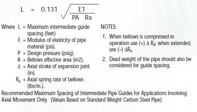
Maximum intermediate guide spacing for any pipe material or thickness may be calculated using the following formula:
SENIOR FLEXONICS WARRANTY IS VOID UNLESS THE ABOVE INSTRUCTIONS ARE FOLLOWED.