
Piping Expansion Joint Design Basics
Piping Flexibility
All materials expand and contract with thermal change. In the case of piping systems, this dimensional change can produce excessive stresses throughout the piping system and at fixed points such as vessels and rotating equipment, as well as within the piping itself.
Pipe Loops
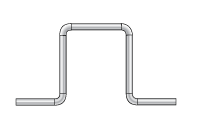 Pipe loops may add the required flexibility to a piping system if space permits, however the initial cost of the additional pipe, elbows and supports must be considered. In addition, increased continuous operating costs due to pressure drop may result from the frictional resistance of the flowing media through additional elbows and pipe. In some cases, pipe diameter must be increased to compensate for losses due to pressure drop.
 A practical and cost effective means of achieving piping system flexibility in a compact design is through the application of expansion joints. The most efficient piping system is the shortest and most directly routed system and expansion joints make this possible.
Expansion joints provide an excellent solution for isolation of settlement, seismic deflection, mechanical vibration and sound attenuation transmission produced by rotating equipment.
Design Basics
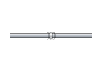
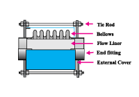
Metal bellows expansion joints consist of a flexible bellows element, appropriate end fittings such as flanges or butt-weld ends to allow connection to the adjacent piping or equipment, and other accessory items that may be required for a particular service application.
Bellows Design
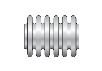 Bellows are manufactured from relatively thin-walled tubing to form a corrugated cylinder. The corrugations, commonly referred to as convolutions, add the structural reinforcement necessary for the thin-wall material to contain system pressure. The bellows designer selects the thickness and convolution geometry to produce a bellows design that approaches, and often exceeds the capacity of the adjoining pipe to contain system pressure at the specified design temperature.
Flexibility of the bellows is achieved through bending of the convolution sidewalls, as well as flexing within their crest and root radii. In most cases, multiple convolutions are required to provide sufficient flexibility to accommodate the expected expansion and contraction of the piping system.
Movement Capabilities
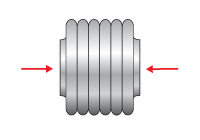
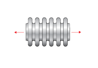
Axial Compression: Reduction of the bellows length due to piping expansion.
Axial Extension: Increase of the bellows length due to pipe contraction.
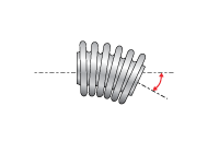
Angular Rotation: Bending about the longitudinal center line of the expansion joint.
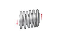
Lateral Offset: Transverse motion which is perpendicular to the plane of the pipe with the expansion joint ends remaining parallel.
Torsion: Twisting about the longitudinal axis of the expansion joint can reduce bellows life or cause expansion joint failure and should be avoided. Expansion joints should not be located at any point in a piping system that would impose torque to the expansion joint as a result of thermal change or settlement.
Cycle Life
In most applications, design movements cause the individual convolutions to deflect beyond their elastic limits, producing fatigue due to plastic deformation, or yielding. One movement cycle occurs each time the expansion joint deflects from the installed length, to the operating temperature length, and then back again to the original installation length.
In the majority of applications, total shutdowns are infrequent, therefore a bellows with a predicted cycle life of one or two thousand cycles is usually sufficient to provide reliable fatigue life for decades of normal service. High cycle life designs may be desirable for service applications that include frequent start up/shut down cycles. The bellows designer considers such design variables as material type, wall thickness, the number of convolutions and their geometry to produce a reliable design for the intended service with a suitable cycle life expectancy.
Squirm
An internally pressurized bellows behaves in a manner similar to that of a slender column under compressive load. At some critical end load, the column will buckle, and in a similar manner, at a sufficient pressure, an internally pressurized bellows that is installed between fixed points will also buckle, or squirm.
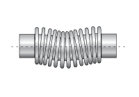
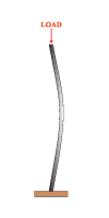 Bellows squirm is characterized by a gross lateral shift of the convolutions off of the longitudinal centerline. Bellows squirm can reduce cycle life, or in extreme cases, produce a catastrophic failure.
To avoid squirm, the bellows designer must limit movement capacity and flexibility to a level that insures that the bellows retains a conservative margin of column stability beyond the required design pressure.
End Fittings
Expansion joints will include appropriate end fittings such as flanges or butt-weld ends that should match the dimensional requirements and materials of the adjoining pipe, or equipment. Small diameter compensators are available with threaded male ends, butt weld ends or copper sweat ends. Threaded flanges may be added to the threaded end compensators if a flanged connection is preferred.
Accessories
For air, steam and other gases
- Up to 6” dia.- 4 ft./sec./inch of diameter
- Above 6” dia. -25 ft/sec
For water and other liquids
- Up to 6” dia. – 2 ft./sec./inch of diameter
- Above 6” dia. -10 ft./sec.
Expansion joints that are installed within ten pipe diameters downstream of elbows, tees, valves or cyclonic devices should be considered to be subject to flow turbulence. The actual flow velocity should be multiplied by 4 to determine if a liner is required per the above guidelines. Actual or factored flow velocities should always be included with design data, particularly flow that exceeds 100 ft./sec. which require heavy gauge liners.
External Covers are mounted at one end of the expansion joint, providing a protective shield that spans the length of the bellows. Covers prevent direct contact with the bellows, offering personnel protection, as well as protection to the bellows from physical damage such as falling objects, weld splatter or arc strikes. Covers also provide a suitable base for
external insulation to be added over an expansion joint. Some insulating materials, if wet, can leach chlorides or other substances that could damage a bellows. Tie rods eliminate pressure thrust and the need for main anchors required in an unrestrained piping system. Axial movement is prevented with the use of tie rods. Designs that have only two tie rods have the additional ability to accommodate angular rotation. Limit rods are similar, however they accommodate a specified axial capability.