
Moment and Torsion Data
The information on the following pages is offered for the benefit of those specifiers who are modeling expansion joints in computer stress programs.
Forces and Moments
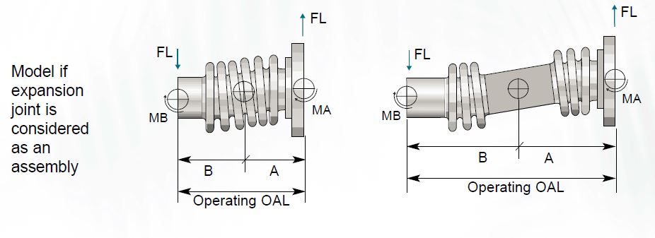
When an expansion joint is offset laterally, the offset force can be assumed to act at a node at the center of the bellows element if the expansion joint is a single bellows type. If the expansion joint is a universal type, the offset force can be assumed to act at a node at the center of the spool that separates the two bellows elements. The expansion joint can be considered as a node with stiffness values acting at the node point.
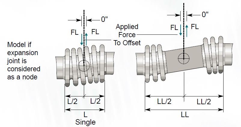
If the expansion joint is being evaluated as an component with offset loads acting at the ends of the assembly, there is a moment that must be considered to properly evaluate the effect of the expansion joint on the adjacent piping. The moment is equal to (the offset force) X (the distance from the end of the assembly to the center of the bellows element) if the expansion joint is a single bellows type. If the expansion joint is a universal, the moment is equal to (the offset force) X (the distance from the center of the center spool to the end of the assembly).
Torsion
Pipe stress programs require that expansion joints be modeled with 6 degrees of stiffness. One of these values is torsional stiffness. The Caesar II pipe stress program by COADE contains a data base that includes all the spring rate values for Senior Flexonics standard bellows elements, including torsion spring rate values. When other software programs are used, the torsional spring rates and torsional limits in the following tables will be helpful.
Torsion can be very damaging to an expansion joint. Torque causes a bellows to want to take a cork screw shape, significantly reducing its pressure carrying capacity. If torsion is present in any amount, it is very important to specify the torsion loading in the inquiry so that the effects of torsion can be taken into account in the product design. If a significant amount of torsion is present, it may be necessary to add hardware to the expansion joint to isolate the bellows element from excessive torque. Expansion joint design engineers assume there is no torsion load on an expansion joint unless a torsion value is specified. Contact
the factory for further information about torsion loading.
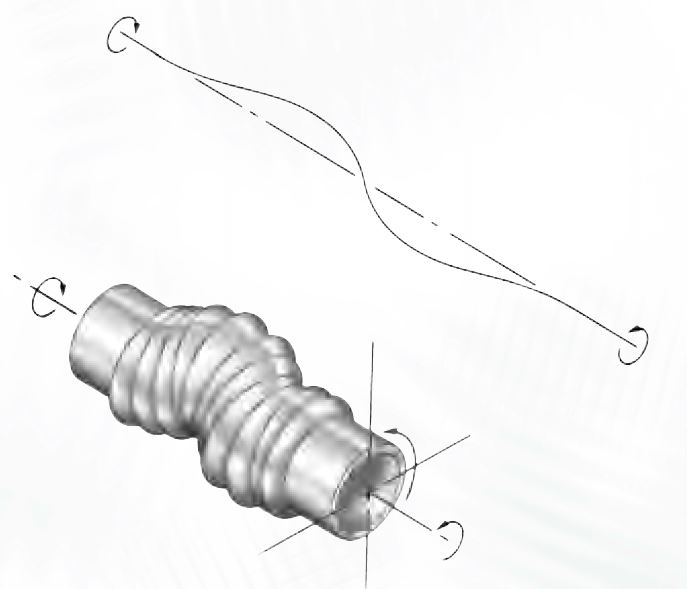
The torsion spring rates are based on torsional stiffness for single bellows elements with no lateral offset. Testing indicates that lateral offset drastically reduces torsional stiffness and the pressure carrying capacity of the bellows.
The torsion data following is applicable to single bellows elements without hinge or gimbal hardware. A universal expansion joint without hardware to resist torque is made up of two single bellows elements. The universal expansion joints specified in this catalog use two 6 convolution bellows elements. Therefore, the torsion criteria for a standard universal expansion joints should be based on a 12-convolution single bellows element if the assembly is being evaluated in total. If each bellows of the universal is being evaluated, use the criteria for a 6 convolution bellows.